HotPDF draws vector graphics by building a path on the current page and then asking for it to be painted. There is no bitmap step in between. A line you draw with MoveTo and LineTo ends up as PDF path operators in the content stream, so it stays a true vector: crisp at 50% zoom, crisp at 1600%, and a fraction of the size a rasterized version would cost. For diagrams, table rules, chart axes, and form decorations, that is exactly what you want, and the API behind it is small enough to learn in one sitting
The whole drawing surface lives on THotPDF.CurrentPage. Between BeginDoc and EndDoc you set color and line width on that page object, lay down geometry, and call a painting operator to commit it. The four primitives you will use most are MoveTo and LineTo for arbitrary paths, Rectangle for boxes, Circle for disks, and the two painting operators Stroke and Fill
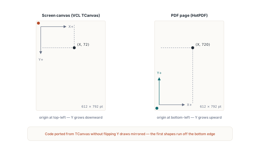
The coordinate system is top-left, like TCanvas
This is the one thing that trips up developers who know the PDF specification. PDF user space puts the origin at the bottom-left corner with Y growing upward, but the HotPDF page drawing calls do not make you work in it. Like the TCanvas you paint controls with, HotPDF measures from the top-left corner of the page in points (1/72 inch), with Y increasing as you move down, and THPDFPage.YProjection flips each Y into PDF user space when it writes the content stream. A point at Y := 72 sits one inch below the top of a US Letter page, which is 792 points tall, and Y := 720 sits one inch above the bottom. If your first drawing comes out mirrored vertically, the usual cause is code copied from a raw PDF example that already subtracts Y from the page height, so HotPDF flips it a second time
The same convention governs TextOut, where by default the Y you pass is the top edge of the text, so text and shapes share one mental model. Plan a layout by deciding where the top of each element sits and the rest follows. The exceptions are the calls that address the PDF file rather than the drawing surface: the page-box setters such as SetCropBox, and the StampLoadedPageText and StampLoadedPageImage family that stamps an already loaded document, take PDF user-space coordinates with the origin at the lower-left
Paths: MoveTo, LineTo, Stroke
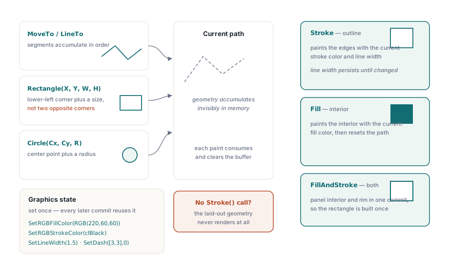
A stroked path is a pen lifted, placed, and dragged. MoveTo lifts the pen and sets the start point without marking anything. Each LineTo extends the current path to a new point. Nothing appears on the page until you call Stroke, which draws the accumulated path using the current stroke color and line width, then clears the path so the next MoveTo starts fresh
var
  Pdf: THotPDF;
begin
  Pdf := THotPDF.Create(nil);
  try
    Pdf.FileName := 'DrawPaths.pdf';
    Pdf.BeginDoc;

    // Line width is in points and applies until you change it.
    Pdf.CurrentPage.SetLineWidth(1.5);
    Pdf.CurrentPage.SetRGBStrokeColor(clBlack);

    // A horizontal rule near the top of the page (Y measured from the top).
    Pdf.CurrentPage.MoveTo(72, 72);
    Pdf.CurrentPage.LineTo(523, 72);
    Pdf.CurrentPage.Stroke;          // commit the path; nothing drew before this

    // A thicker connected polyline: three segments in one path.
    Pdf.CurrentPage.SetLineWidth(3);
    Pdf.CurrentPage.SetRGBStrokeColor(RGB(30, 90, 200));
    Pdf.CurrentPage.MoveTo(72, 152);
    Pdf.CurrentPage.LineTo(172, 102);
    Pdf.CurrentPage.LineTo(272, 172);
    Pdf.CurrentPage.LineTo(372, 112);
    Pdf.CurrentPage.Stroke;

    Pdf.EndDoc;
  finally
    Pdf.Free;
  end;
end;
Two details save real debugging time. Line width is state, not an argument: SetLineWidth sets it once and every subsequent Stroke uses that value until you change it again, which is why the polyline above is thicker than the rule. And the path resets after each Stroke, so a forgotten Stroke means the geometry you so carefully laid out never renders at all. If a shape is missing from the output, the painting call is the first place to look
The coordinates are points, and points are fractional. MoveTo and LineTo accept Single values, so a hairline at 0.5 points or a position at 72.25 is legal and meaningful, not rounded away to the nearest whole unit. That precision matters in two opposite directions. A line width below about 0.5 can render as a device-dependent thinnest-possible line that disappears on screen and reappears when printed, so a visible rule wants a width you set on purpose rather than the default. At the other end, snapping table rules and gridlines to whole-point coordinates keeps a dense grid from looking slightly uneven where adjacent lines round differently. Decide the grid spacing in points up front and the rest of the layout inherits it
Filled shapes and color
Closed primitives can be filled instead of outlined. Rectangle takes a position and a size, Circle takes a center and a radius, and either one is committed with Fill, which paints the interior in the current fill color, or with Stroke for an outline only. Fill color and stroke color are separate pieces of state, set with SetRGBFillColor and SetRGBStrokeColor, both of which take a single TColor. That means you can reuse Delphi's color constants and the RGB helper directly
// Rectangle(X, Y, Width, Height): X and Y are the top-left corner.
Pdf.CurrentPage.SetRGBFillColor(RGB(220, 60, 60));
Pdf.CurrentPage.Rectangle(72, 202, 160, 90);
Pdf.CurrentPage.Fill;

// Circle(X, Y, Radius): X and Y are the center.
Pdf.CurrentPage.SetRGBFillColor(clNavy);
Pdf.CurrentPage.Circle(420, 247, 45);
Pdf.CurrentPage.Fill;

// Outline only: set a stroke color and a width, then Stroke.
Pdf.CurrentPage.SetLineWidth(2);
Pdf.CurrentPage.SetRGBStrokeColor(clBlack);
Pdf.CurrentPage.Rectangle(72, 332, 160, 60);
Pdf.CurrentPage.Stroke;
Watch the argument shape on Rectangle. It is position-plus-size, X, Y, Width, Height, not two opposite corners. The TCanvas.Rectangle that Delphi developers know takes (Left, Top, Right, Bottom), so muscle memory will hand HotPDF a second corner where it expects a width and a height, and the box comes out the wrong size. The (X, Y) pair is the top-left corner, consistent with the page origin, and the box extends right and down from it. For a circle, (X, Y) is the center and the third argument is the radius in points
One color choice the original sample got wrong
An older version of this example seeded colors with Random($FFFFFF) on every shape. It looks lively, and it is the wrong instinct for generated documents. A PDF you build from code is usually something you also want to test, and random fill colors make the output impossible to compare run to run: a byte-for-byte diff against a known-good file fails every time, for no real reason. Pick explicit colors. When you want variety across a series of shapes, drive it from your data or a fixed palette array, so the same input always produces the same file. Determinism is worth more than novelty when the artifact moves through a release pipeline
Putting the primitives together: a callout box
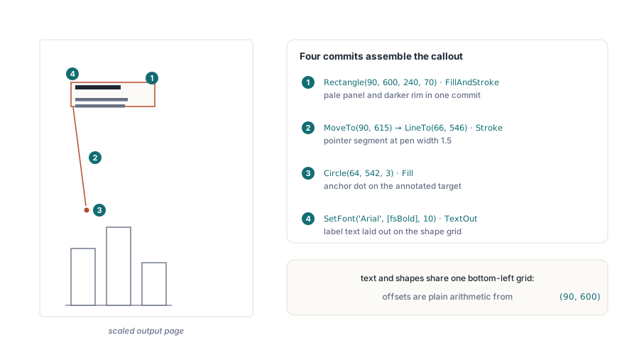
Each primitive is simple on its own; the payoff shows when a handful of them compose into something a report actually needs. A callout, the annotated box that points at a figure and explains it, uses everything covered so far: a filled rectangle with a border, a stroked pointer line, a dot to anchor the pointer, and text laid out inside the box using the same top-left coordinates the shapes use. FillAndStroke earns its place here, painting the interior and the outline of one path in a single commit instead of building the rectangle twice
var
  Pdf: THotPDF;
begin
  Pdf := THotPDF.Create(nil);
  try
    Pdf.FileName := 'Callout.pdf';
    Pdf.BeginDoc;

    // 1. The box: pale fill plus a visible border, one path, one commit.
    //    Rectangle is top-left corner plus size, Y measured from the top
    Pdf.CurrentPage.SetRGBFillColor(RGB(255, 244, 214));   // pale amber panel
    Pdf.CurrentPage.SetRGBStrokeColor(RGB(180, 130, 40));  // darker rim
    Pdf.CurrentPage.SetLineWidth(1);
    Pdf.CurrentPage.Rectangle(90, 122, 240, 70);
    Pdf.CurrentPage.FillAndStroke;

    // 2. The pointer: one stroked segment from the box edge down
    //    toward the thing being annotated
    Pdf.CurrentPage.SetLineWidth(1.5);
    Pdf.CurrentPage.MoveTo(90, 177);        // left edge of the box
    Pdf.CurrentPage.LineTo(66, 246);
    Pdf.CurrentPage.Stroke;

    // 3. A filled dot anchors the pointer at its target
    Pdf.CurrentPage.SetRGBFillColor(RGB(180, 130, 40));
    Pdf.CurrentPage.Circle(64, 250, 3);
    Pdf.CurrentPage.Fill;

    // 4. The label, positioned relative to the box's top-left corner.
    //    Text and shapes share one coordinate system, so the offsets
    //    are plain arithmetic against (90, 122); each Y is a text top
    Pdf.CurrentPage.SetFont('Arial', [fsBold], 10);
    Pdf.CurrentPage.TextOut(102, 134, 0, 'Check this total');
    Pdf.CurrentPage.SetFont('Arial', [], 9);
    Pdf.CurrentPage.TextOut(102, 152, 0, 'The rounding rule changed in the');
    Pdf.CurrentPage.TextOut(102, 164, 0, 'June release; verify against v2.1');

    Pdf.EndDoc;
  finally
    Pdf.Free;
  end;
end;
Notice how little state management the composite needs. Fill color, stroke color, and line width are each set immediately before the shape that uses them, so every block of the drawing reads as a self-contained unit and can be reordered or extracted into a helper without dragging hidden state along. Wrap this in a procedure taking the anchor point and the strings, and you have a reusable diagram annotation for the cost of forty lines
Where vector drawing pays off, and where it does not
Reach for these path and shape calls when the geometry is generated: chart gridlines and bars, the ruled lines of an invoice table, callout boxes on a diagram, a logo mark expressed as a handful of paths. All of it scales without blur and adds almost nothing to the file size, because a rectangle is a few numbers rather than thousands of pixels. The flip side is honest too. If what you actually have is a photograph or a screenshot, draw it as an image with AddImage and ShowImage instead; tracing a bitmap with vector calls buys you nothing. The straight segments, rectangles, and circles above carry the large majority of real reporting work, and the three refinements developers ask about next, curves, dash patterns, and transparency, sit on the same page object
Curves, dashes, and transparency in brief
Freeform curves extend the same path machinery you already have. CurveToC(X1, Y1, X2, Y2, X3, Y3) appends a cubic Bezier segment from the current point to (X3, Y3), bending toward the two control points, and the shorthand variants CurveToV and CurveToY cover the cases where one control point coincides with an endpoint. A path can mix LineTo and CurveToC segments freely before a single Stroke or Fill commits it, which is how rounded corners and smooth chart lines are built
Dashed strokes are state, exactly like line width. SetDash([3, 3], 0) switches every subsequent stroke to a three-point-on, three-point-off pattern, the array spelling out the on/off run lengths in points and the second argument phasing where the cycle starts; NoDash returns the pen to a solid line. Set it, stroke the gridlines that want it, and reset it before the next solid rule, or the dash quietly infects everything that follows
Transparency runs through a named graphics state rather than a color argument, because alpha in PDF is a property of the graphics state dictionary. Register one on the document with RegisterExtGState, passing a fill alpha and a stroke alpha between 0 and 1, then apply the name it returns with CurrentPage.SetGraphicsState; fills and strokes from that point paint at the registered opacity. It is a heavier ceremony than the color setters, and worth it the first time a highlight bar has to sit over text without hiding it
The remaining habit worth keeping is verification. Generated geometry can pass on your machine and fail on a customer's, usually over font substitution in any text you mix in or a page-size assumption that does not hold. Open the finished file at a few zoom levels to confirm the edges stay clean, and check that every shape lands inside the margin box you intended. With a deterministic color scheme, that check can be automated against a reference PDF rather than eyeballed
The MoveTo, LineTo, Stroke, Fill, and color calls shown here are part of the HotPDF Delphi Component for Delphi and C++Builder