Technical Article

PDF Graphics Explained: Understanding PDF Visual Elements

· PDF Internals

PDF Graphics: From Basic Paths to Advanced Visual Effects

Discover the fascinating world of PDF graphics – from basic shapes to complex visual effects. This comprehensive guide reveals how PDFs create stunning visuals through elegant code structures.

The Foundation of Digital Documents

When you open a PDF document, you’re witnessing the result of a sophisticated graphics system that has been quietly powering digital documents for decades. Behind every line, curve, and visual element lies a carefully orchestrated set of instructions that transform simple commands into rich visual content.

PDF graphics aren’t just about displaying static images – they represent a complete programming language for visual content. Whether you’re a developer working with PDF generation, a designer curious about the technical underpinnings, or simply someone fascinated by how digital documents work, this guide will illuminate the elegant mechanics that make PDF graphics possible.

In this comprehensive exploration, we’ll journey through the core concepts that drive PDF graphics, from the fundamental building blocks of paths and operators to advanced techniques like transparency, transformations, and pattern fills. You’ll discover how PDF’s graphics model creates everything from simple geometric shapes to complex interactive elements.

The Building Blocks: PDF Graphics Fundamentals

What Makes PDF Graphics Special?

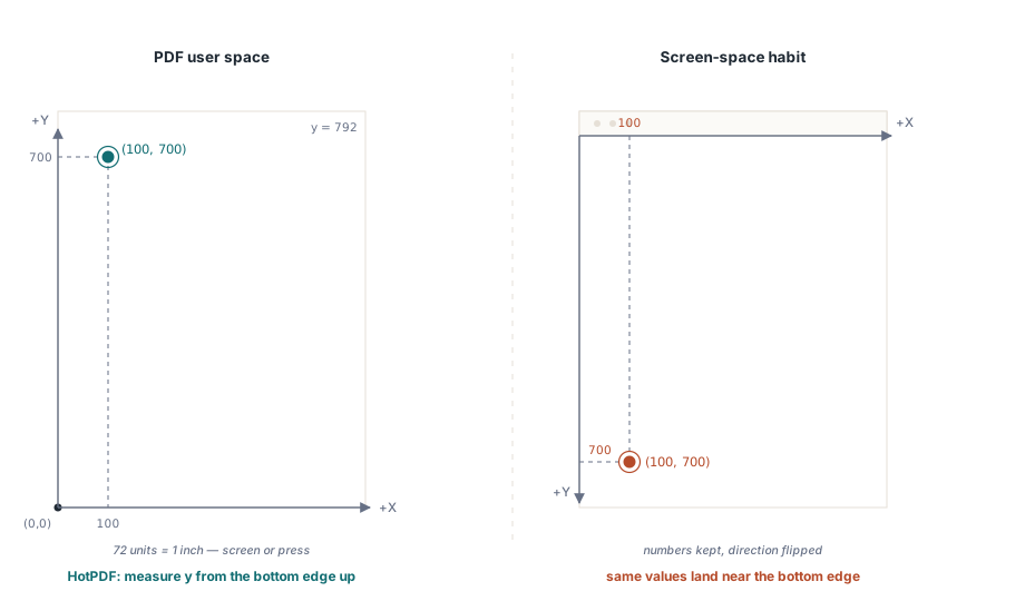
PDF graphics operate on a unique model that combines the precision of vector graphics with the flexibility of a programming language. Unlike bitmap images that store colour information for each pixel, PDF graphics use mathematical descriptions to define shapes, colours, and visual effects.

This approach offers several key advantages:

  • Scalability: Graphics remain crisp at any zoom level
  • Efficiency: Complex shapes are described with minimal data
  • Precision: Mathematical accuracy ensures consistent rendering
  • Flexibility: Dynamic effects and transformations are possible

The Graphics State: Your Canvas Configuration

At the heart of PDF graphics lies the concept of the “graphics state” – think of it as the current configuration of your digital canvas. This state includes essential properties like:

  • Current Transformation Matrix (CTM): Defines how coordinates map to the page
  • Colour Space: Determines how colours are interpreted and displayed
  • Line Properties: Width, dash patterns, and join styles
  • Fill Properties: Colours, patterns, and transparency settings

Understanding the graphics state is crucial because every operation you perform affects or depends on these settings. It’s like having a sophisticated drawing program where you can save and restore different tool configurations instantly.

Content Streams: The Language of PDF Graphics

PDF graphics are defined through content streams – sequences of operators and operands that describe how to construct visual elements. Think of content streams as a specialised programming language designed specifically for graphics operations.

The Anatomy of a Content Stream

A content stream consists of operators (commands) preceded by their operands (parameters). This postfix notation might seem unusual at first, but it provides a clean and efficient way to describe complex graphics operations.

Here’s a simple example that demonstrates the basic structure:

1
2
3
4
5
100 100 m    % Move to point (100, 100)
200 200 l    % Draw line to (200, 200)  
300 100 l    % Draw line to (300, 100)
h            % Close the path
S            % Stroke the path

This sequence creates a simple triangle by moving to a starting point, drawing lines to form the shape, closing the path, and finally stroking it to make it visible.

Understanding PDF Operators

PDF operators are the verbs of the graphics language. Each operator performs a specific action, from basic drawing commands to complex transformations. The beauty of this system lies in its composability – simple operators can be combined to create sophisticated visual effects.

Let’s explore how these concepts work together to create our first PDF graphic:

A simple PDF path showing a curved shape with stroke and fill, demonstrating basic PDF graphics operators in action
Figure 1. A simple path in PDF graphics showing how basic operators create visual elements

This figure illustrates the fundamental concept of PDF paths – the building blocks from which all PDF graphics are constructed. The shape you see is created through a series of simple commands that define points, curves, and visual properties.

Paths and Painting: Creating Visual Elements

The Path Construction Process

In PDF graphics, creating visual content is typically a two-step process: first you construct a path (defining the shape), then you paint it (making it visible). This separation provides incredible flexibility in how graphics elements are rendered.

Path Construction Operators

Path construction uses a set of intuitive operators that mirror traditional drawing techniques:

  • m (moveto): Lifts the “pen” and moves to a new position without drawing
  • l (lineto): Draws a straight line from the current position to a new point
  • c (curveto): Creates smooth curves using Bézier curve mathematics
  • h (closepath): Connects the current position back to the path’s starting point

Let’s examine a practical example that creates a curved shape:

1
2
3
4
200 250 m           % Start at point (200, 250)
300 350 400 450 500 250 c   % Create a Bézier curve
400 250 300 200 y   % Add another curve segment  
h                   % Close the path

This sequence demonstrates how PDF uses mathematical precision to define smooth curves. The Bézier curve operator c takes six parameters: two control points and an end point, allowing for sophisticated curve definition.

Path Painting Operations: Bringing Shapes to Life

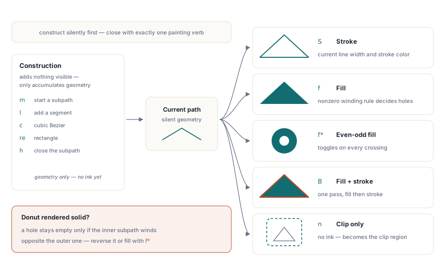
Once you’ve constructed a path, the next step is to make it visible through painting operations. PDF provides several fundamental painting operators that determine how paths appear on the page. Understanding these operators is essential for creating effective PDF graphics.

The Core Painting Operators

PDF offers three primary ways to paint a path, each serving different visual purposes:

Three PDF path painting operations showing fill only, stroke only, and combined fill and stroke techniques with colorful geometric shapes
Figure 2. The three fundamental path painting operations in PDF graphics

Fill Operations (f, F, f*, F*)

Fill operations paint the interior of a path with the current fill colour. The basic f operator uses the non-zero winding rule to determine which areas are inside the path, while f* uses the even-odd rule. This distinction becomes crucial when dealing with complex shapes that intersect themselves.

1
2
3
4
5
200 250 m           % Start the path
300 350 400 450 500 250 c   % Create curves
400 250 300 200 y   % Complete the shape
h                   % Close the path
f                   % Fill the path

Stroke Operations (S, s)

Stroke operations paint the outline of a path using the current stroke colour and line properties. The line width, dash pattern, and join style all affect how the stroke appears. This operation is perfect for creating outlines, borders, and linear elements.

1
2
3
4
5
6
2.0 w              % Set line width to 2 points
200 250 m          % Start the path  
300 350 400 450 500 250 c   % Create the shape
400 250 300 200 y  % Complete curves
h                  % Close path
S                  % Stroke the path

Combined Fill and Stroke (B, B*, b, b*)

The B operator combines both fill and stroke operations in a single command, allowing you to create shapes with both interior colour and visible outlines. This is often the most visually appealing option for complex graphics.

1
2
3
4
5
6
7
8
2.0 w              % Set stroke width
0.8 g              % Set fill to light gray
0 G                % Set stroke to black
200 250 m          % Begin path construction
300 350 400 450 500 250 c
400 250 300 200 y
h                  % Close path
B                  % Fill and stroke

Path Painting Rules: Understanding Fill Behaviour

When paths intersect or contain complex nested areas, PDF uses specific rules to determine which areas should be filled:

Non-Zero Winding Rule

The non-zero winding rule (used by f and B) determines fill areas by tracking the direction of path segments. This rule typically produces intuitive results for most shapes and is the default choice for most applications.

Even-Odd Rule

The even-odd rule (used by f* and B*) alternates between filled and unfilled areas based on the number of path crossings. This rule is useful for creating shapes with holes or complex patterns.

Colours and Colour Spaces: Painting with Precision

Colour in PDF graphics goes far beyond simple RGB values. PDF supports multiple colour spaces, each optimised for different use cases and output requirements. Understanding these colour spaces is essential for creating graphics that display and print consistently across different devices and contexts.

Device Colour Spaces

Device colour spaces directly correspond to the capabilities of specific output devices:

DeviceGray

The simplest colour space, DeviceGray represents grayscale values from 0 (black) to 1 (white). This colour space is perfect for monochrome graphics and text, offering excellent performance and small file sizes.

1
2
/DeviceGray cs     % Select DeviceGray colour space
0.5 g              % Set gray level to 50%

DeviceRGB

DeviceRGB uses the familiar red, green, and blue colour model. Each component ranges from 0 to 1, allowing for 16.7 million colour combinations. This colour space is ideal for screen display and digital graphics.

1
2
3
/DeviceRGB cs      % Select RGB colour space  
0.2 0.6 0.8 rg     % Set fill colour (blue-green)
0.8 0.2 0.1 RG     % Set stroke colour (red)

DeviceCMYK

DeviceCMYK represents colours using cyan, magenta, yellow, and black components – the standard for professional printing. This colour space ensures accurate colour reproduction in print environments.

1
2
/DeviceCMYK cs     % Select CMYK colour space
0.2 0.8 0.0 0.1 k  % Set fill colour (magenta-heavy)

Colour Selection Operators

PDF provides specific operators for setting colours in different contexts:

  • g, rg, k: Set fill colours for Gray, RGB, and CMYK respectively
  • G, RG, K: Set stroke colours (capital letters)
  • cs, CS: Select colour spaces for fill and stroke operations
  • sc, SC: Set colours in the current colour space

This systematic approach to colour management ensures that your PDF graphics maintain colour accuracy across different viewing and printing scenarios.

PDF color spaces comparison showing DeviceGray, DeviceRGB, and DeviceCMYK examples with sample colors and operator syntax
Figure 3. Comparison of PDF colour spaces and their respective operators

Practical Colour Management

Effective colour management in PDF graphics requires understanding when to use each colour space:

  • Use DeviceGray for monochrome content, text, and when file size is a concern
  • Use DeviceRGB for digital displays, web graphics, and screen-optimised content
  • Use DeviceCMYK for print production, professional publishing, and colour-critical applications

Remember that colour space selection affects not only appearance but also file size and processing performance. Choose the most appropriate colour space for your specific use case.

Coordinate Transformations: Reshaping Reality

One of PDF’s most powerful features is its coordinate transformation system. Through mathematical transformations, you can scale, rotate, translate, and skew graphics elements with precision. This capability transforms PDF from a simple drawing system into a sophisticated graphics programming environment.

The Current Transformation Matrix (CTM)

At the core of PDF’s transformation system lies the Current Transformation Matrix (CTM) – a 3×3 matrix that defines how coordinates in your graphics commands map to actual positions on the page. Every coordinate you specify is transformed through this matrix before being rendered.

The transformation matrix uses the following mathematical representation:

1
2
3
[a  b  0]
[c  d  0]   where: [x' y' 1] = [x y 1] × CTM
[e  f  1]

This matrix enables four fundamental transformation types:

Translation: Moving Objects

Translation moves objects from one position to another without changing their size or orientation. This is accomplished by modifying the e and f components of the transformation matrix.

1
1 0 0 1 100 50 cm    % Translate by (100, 50)

Scaling: Resizing Objects

Scaling changes the size of objects by multiplying coordinates by scale factors. Uniform scaling maintains aspect ratios, while non-uniform scaling can stretch or compress objects.

1
2 0 0 1.5 0 0 cm     % Scale x by 2, y by 1.5

Rotation: Spinning Objects

Rotation transforms objects around a specific point (typically the origin). The rotation angle is specified in radians, with positive values indicating counterclockwise rotation.

1
0.707 0.707 -0.707 0.707 0 0 cm  % Rotate 45° (π/4 radians)

Skewing: Creating Perspective Effects

Skewing transforms create slanted or perspective effects by shifting coordinates along one axis relative to the other.

1
1 0.5 0 1 0 0 cm     % Skew along x-axis

PDF coordinate transformations showing original shape, translation, scaling, rotation, and combined transformation examples with matrix operators
Figure 4. PDF coordinate transformations: translation, scaling, rotation, and combined effects

Graphics State Management

PDF provides elegant mechanisms for managing transformation states through the q (save) and Q (restore) operators. These operators work like a stack, allowing you to:

  • Save current state: q pushes the current graphics state onto a stack
  • Apply transformations: Modify the CTM for specific operations
  • Restore previous state: Q pops the saved state from the stack

This approach enables complex graphics compositions while maintaining clean, predictable coordinate systems:

1
2
3
4
5
q                    % Save current graphics state
2 0 0 2 100 100 cm   % Scale by 2 and translate
% ... draw scaled content ...
Q                    % Restore original state
% Continue with original coordinate system

Advanced Graphics Features: Beyond Basic Shapes

While basic path construction and painting form the foundation of PDF graphics, the format offers sophisticated features that enable complex visual effects and professional-quality output. These advanced capabilities transform PDF from a simple document format into a powerful graphics platform.

Clipping Paths: Controlled Visibility

Clipping paths allow you to restrict drawing operations to specific regions of the page. This powerful technique enables complex layouts, masked effects, and precise content positioning.

Creating Clipping Regions

The clipping process involves three steps:

  1. Define the clipping path: Use standard path construction operators
  2. Set the clipping region: Apply the W (non-zero) or W* (even-odd) operator
  3. Draw clipped content: All subsequent drawing is restricted to the clipping area

1
2
3
4
5
6
7
8
% Define triangular clipping path
200 100 m
200 500 l  
500 100 l
h              % Close the path
W              % Set as clipping region
S              % Stroke the clipping boundary
% All subsequent drawing is clipped to this triangle

Nested Clipping

Clipping regions can be nested using the graphics state stack. Each new clipping path intersects with the existing clipping region, creating increasingly restrictive drawing areas.

Transparency and Blending

PDF’s transparency model enables sophisticated visual effects through alpha compositing and blend modes. This system allows for realistic overlays, shadows, and complex layering effects.

Alpha Transparency

Transparency in PDF is controlled through the external graphics state mechanism:

1
2
3
4
5
<< /ExtGState          % Define external graphics state
   << /gs1             % Name for this state collection
      << /ca 0.5 >>    % 50% fill transparency
   >>
>>

The transparency is then applied using the gs operator:

1
2
3
/gs1 gs               % Apply transparency state
0.75 g                % Set light gray fill
% Draw semi-transparent content

Transparency Properties

  • /ca: Controls fill transparency (0 = fully transparent, 1 = fully opaque)
  • /CA: Controls stroke transparency
  • /BM: Specifies blend mode for colour mixing

Patterns and Shadings: Advanced Fill Techniques

Beyond solid colours, PDF supports sophisticated fill patterns and gradient shadings that can transform simple shapes into visually rich elements. These features enable everything from subtle gradients to complex repeating patterns.

Understanding PDF Patterns

PDF supports two primary pattern types, each serving different visual purposes:

Tiling Patterns (Type 1)

Tiling patterns repeat a small “pattern cell” across the filled area. These patterns are perfect for backgrounds, textures, and decorative elements.

Shading Patterns (Type 2)

Shading patterns create smooth colour transitions and gradients. PDF supports several shading types:

  • Axial Shading (Type 2): Linear gradients between two points
  • Radial Shading (Type 3): Circular gradients from centre to edge
  • Function-based Shading (Type 1): Mathematically defined colour transitions
  • Mesh-based Shadings (Types 4-7): Complex colour interpolations

Implementing Axial Shadings

Axial shadings create linear gradients that transition smoothly between colours:

1
2
3
4
5
6
7
8
9
10
11
12
13
14
15
16
/Pattern              % Switch to pattern colour space
<<
  /GradientShading    % Pattern name
  <<
    /Type /Pattern
    /PatternType 2    % Shading pattern
    /Shading
    <<
      /ColorSpace /DeviceGray
      /ShadingType 2  % Axial shading
      /Coords [150 200 450 500]  % Start and end points
      /Function << /FunctionType 2 /N 1 /Domain [0 1] >>
      /Extend [true true]
    >>
  >>
>>

Once defined, the pattern is applied like any other colour:

1
2
3
/Pattern cs           % Select pattern colour space
/GradientShading scn  % Apply our gradient pattern
% Draw shape with gradient fill

Radial Shading Effects

Radial shadings create circular gradients, perfect for spotlight effects, radial backgrounds, and three-dimensional illusions:

1
2
/ShadingType 3        % Radial shading
/Coords [400 400 0 400 400 200]  % Inner and outer circles

This defines a radial gradient centred at (400, 400) with inner radius 0 and outer radius 200.

PDF advanced graphics features showing clipping paths, transparency effects, axial shading gradients, and radial shading patterns
Figure 5. Advanced PDF graphics: clipping paths, transparency, and gradient patterns

Practical Shading Implementation

When implementing shadings in your PDF documents, consider these optimisation strategies:

Performance Considerations

  • Shading Complexity: Simple axial and radial shadings render faster than complex mesh-based patterns
  • Colour Space Selection: Device-dependent colour spaces (DeviceRGB, DeviceCMYK) offer better performance than ICC-based profiles
  • Function Optimisation: Use linear interpolation functions when possible to minimize computational overhead

Quality vs. File Size Trade-offs

Gradient quality and file size often require careful balancing:

1
2
3
4
% Smooth gradient with many colour stops
/Function << /FunctionType 3 /Domain [0 1]
              /Functions [func1 func2 func3 func4]
              /Bounds [0.25 0.5 0.75] >>

Versus a simpler approach for smaller files:

1
2
% Simple two-colour gradient
/Function << /FunctionType 2 /Domain [0 1] /N 1 >>

XObjects: Reusable Content and External Resources

XObjects represent one of PDF’s most powerful features for creating efficient, maintainable documents. By encapsulating graphics, images, and text as reusable objects, XObjects enable sophisticated document architectures while minimizing file size and complexity.

Understanding XObject Types

PDF defines several XObject types, each optimised for specific content types:

Form XObjects: Reusable Graphics

Form XObjects encapsulate graphics content that can be reused throughout a document. They’re perfect for:

  • Logos and branding elements that appear on multiple pages
  • Complex graphics that would otherwise require repeated code
  • Template elements like headers, footers, and borders
  • Layered content that can be easily modified or replaced

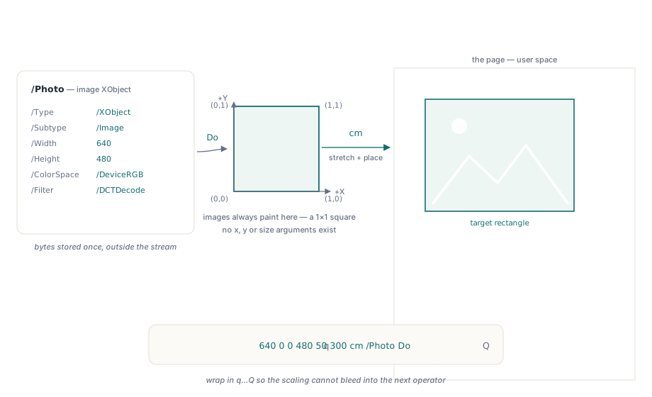
Image XObjects: Optimised Images

Image XObjects provide efficient storage and rendering of bitmap images:

  • Automatic compression based on image characteristics
  • Colour space optimisation for print and display
  • Scaling and transformation without quality loss
  • Mask support for transparency effects

Form XObject Implementation

Creating and using Form XObjects involves a two-step process: definition and invocation.

Step 1: Define the Form XObject

Form XObjects are defined in the PDF’s XObject dictionary:

1
2
3
4
5
6
7
8
9
/XObject <<
  /Logo <<
    /Type /XObject
    /Subtype /Form
    /BBox [0 0 200 100]      % Bounding box
    /Matrix [1 0 0 1 0 0]    % Transformation matrix
    /Length 45
  >>
>>

The Form XObject’s content stream contains the actual graphics commands:

1
2
3
4
5
6
7
8
stream
q                            % Save graphics state
1 0 0 RG                     % Red stroke colour
2 w                          % 2-point line width
10 10 180 80 re              % Rectangle path
S                            % Stroke the rectangle
Q                            % Restore graphics state
endstream

Step 2: Invoke the Form XObject

Once defined, Form XObjects are invoked using the Do operator:

1
2
3
4
q                            % Save current state
2 0 0 2 100 100 cm          % Scale by 2, translate to (100,100)
/Logo Do                     % Invoke the Logo XObject
Q                            % Restore state

Image XObject Integration

Image XObjects handle bitmap images with sophisticated compression and colour management:

1
2
3
4
5
6
7
8
9
10
11
12
/XObject <<
  /Photo <<
    /Type /XObject
    /Subtype /Image
    /Width 640
    /Height 480
    /BitsPerComponent 8
    /ColorSpace /DeviceRGB
    /Filter /DCTDecode        % JPEG compression
    /Length 45670
  >>
>>

Image XObjects are invoked similarly to Form XObjects:

1
2
3
4
q
640 0 0 480 50 300 cm        % Scale and position the image
/Photo Do                     % Render the image
Q

XObject Optimisation Strategies

Memory Management

Effective XObject usage can dramatically reduce memory footprint:

  • Share common elements: Define logos, headers, and repeated graphics once
  • Optimise image formats: Use JPEG for photographs, PNG for graphics with transparency
  • Consider resolution: Match image resolution to intended display size

Rendering Performance

XObjects can significantly improve rendering performance when used strategically:

  • Cache frequently used elements: Viewers can cache XObjects for faster repeated rendering
  • Minimize transformation changes: Consistent transformations improve caching efficiency
  • Group related content: Combine related elements into single Form XObjects
PDF XObjects showing Form XObjects for reusable graphics, Image XObjects for optimized images, benefits list, and performance comparison
Figure 6. PDF XObjects: Form XObjects, Image XObjects, and their performance benefits

Advanced XObject Techniques

Nested Form XObjects

Form XObjects can contain references to other XObjects, enabling sophisticated content hierarchies:

1
2
3
4
5
6
7
8
9
10
11
12
13
14
15
% Master template containing multiple sub-elements
/XObject <<
  /HeaderTemplate << ... >>
  /FooterTemplate << ... >>
  /MainContent <<
    /Type /XObject
    /Subtype /Form
    % References other XObjects
    stream
    /HeaderTemplate Do
    % ... main content ...
    /FooterTemplate Do
    endstream
  >>
>>

Conditional XObject Usage

XObjects can be conditionally applied based on document properties or user preferences, enabling adaptive content rendering without duplicating resources.

Best Practices and Optimisation Strategies

Creating efficient PDF graphics requires understanding both the technical capabilities of the format and the practical considerations of real-world usage. These best practices will help you create professional-quality PDFs that render quickly and consistently across different viewers and devices.

Graphics Performance Optimisation

Path Complexity Management

Complex paths with thousands of points can significantly impact rendering performance. Consider these optimisation strategies:

  • Simplify curves: Use cubic Bézier curves instead of multiple small line segments
  • Optimise point density: Remove unnecessary intermediate points while maintaining visual fidelity
  • Consider rasterization: For extremely complex paths, converting to images may improve performance

1
2
3
4
5
6
7
% Inefficient: Many small line segments
100 100 m
101 101 l 102 102 l 103 103 l ... (hundreds of points)
 
% Efficient: Smooth curve
100 100 m
110 105 120 110 150 120 c        % Single cubic curve

Colour Space Selection Guidelines

Choose colour spaces based on your document’s intended use:

Use Case Recommended Colour Space Benefits
Screen Display DeviceRGB Fast rendering, natural colour appearance
Professional Printing DeviceCMYK Print-optimised colours, industry standard
Grayscale Documents DeviceGray Smaller file size, faster processing
Colour-Critical Work ICC-based Precise colour reproduction, calibrated output

File Size Optimisation

Content Stream Efficiency

Minimize redundant operations in your content streams:

1
2
3
4
5
6
7
8
9
10
% Inefficient: Repeated colour changes
1 0 0 rg  100 100 50 50 re f     % Red rectangle
1 0 0 rg  200 100 50 50 re f     % Same red, redundant
1 0 0 rg  300 100 50 50 re f     % Same red, redundant
 
% Efficient: Set colour once
1 0 0 rg                         % Set red once
100 100 50 50 re f               % Rectangle 1
200 100 50 50 re f               % Rectangle 2  
300 100 50 50 re f               % Rectangle 3

Strategic Graphics State Management

Use the graphics state stack (q/Q) strategically to minimize state changes:

1
2
3
4
5
6
7
8
9
q                                % Save initial state
% Apply common transformations/settings
2 w                              % Set line width once
0.5 G                            % Set gray level once
 
% Draw multiple elements with shared properties
100 100 m 200 200 l S            % Line 1
150 150 m 250 250 l S            % Line 2
Q                                % Restore state efficiently

Cross-Platform Compatibility

Font Handling Best Practices

While this article focuses on graphics, text rendering affects overall document reliability:

  • Embed fonts: Ensure consistent appearance across systems
  • Use standard fonts: Fall back to widely available typefaces
  • Consider font subsetting: Include only necessary characters to reduce file size

Viewer Compatibility Considerations

Different PDF viewers may interpret graphics commands slightly differently:

  • Test across viewers: Verify appearance in Adobe Reader, browser viewers, and mobile apps
  • Avoid edge cases: Some rarely-used operators may not be universally supported
  • Use standard patterns: Stick to well-established graphics patterns for maximum compatibility

Troubleshooting Common Graphics Issues

Understanding common graphics problems and their solutions can save significant development time and ensure reliable document rendering across different environments.

Path Rendering Problems

Issue: Paths Not Appearing

Common causes and solutions:

  • Missing painting operator: Ensure you use S, f, or B to actually render paths
  • Invalid coordinates: Check that path coordinates are within the page boundaries
  • Zero-width strokes: Verify line width is set appropriately with the w operator

1
2
3
4
5
% Problem: Path defined but not painted
100 100 m 200 200 l              % Path exists but invisible
 
% Solution: Add painting operator
100 100 m 200 200 l S            % Now the line will appear

Issue: Unexpected Clipping

Graphics appearing cut off or invisible due to clipping issues:

  • Check clipping paths: Ensure clipping regions are appropriate for your content
  • Verify coordinate systems: Transformations may place objects outside visible areas
  • Review graphics state stack: Unbalanced q/Q operations can cause issues

Colour and Transparency Issues

Issue: Colours Not Matching Expected Output

Debugging steps:

  1. Verify colour space is set correctly before colour values
  2. Check that colour values are within valid ranges for the colour space
  3. Consider colour profile differences between creation and viewing environments

Issue: Transparency Not Working

Common transparency problems and solutions:

  • Missing ExtGState: Transparency requires proper external graphics state definition
  • Viewer limitations: Some older viewers have limited transparency support
  • Blend mode conflicts: Ensure blend modes are compatible with your content

Performance and Rendering Issues

Issue: Slow Rendering Performance

Optimisation strategies:

  • Reduce path complexity: Simplify complex curves and eliminate redundant points
  • Optimise XObject usage: Reuse common elements instead of duplicating code
  • Consider rasterization: Convert extremely complex vector graphics to images
  • Minimize transparency layers: Complex transparency hierarchies can impact performance

Conclusion: Mastering PDF Graphics

PDF graphics represent a sophisticated balance of flexibility, efficiency, and cross-platform reliability. From basic path construction to advanced features like transparency blending and reusable XObjects, the PDF format provides a comprehensive toolkit for creating professional-quality documents.

Key Takeaways

Throughout this exploration of PDF graphics, several fundamental principles emerge:

1. Layered Architecture

PDF’s graphics model builds systematically from simple primitives to complex effects. Understanding this layered approach—from basic paths to colour spaces to transformations—enables you to tackle even the most sophisticated graphics requirements.

2. Efficiency Through Reuse

Features like XObjects, patterns, and graphics state management aren’t just convenience tools—they’re essential for creating maintainable, efficient documents. The investment in understanding these features pays dividends in file size reduction and rendering performance.

3. Precision and Control

Unlike many graphics formats, PDF gives you direct control over every aspect of rendering. This precision enables everything from pixel-perfect layouts to complex colour management, but it also requires understanding the implications of your choices.

Looking Forward: Advanced Applications

The concepts covered in this article form the foundation for more advanced PDF applications:

  • Interactive documents: Combining graphics with form fields and annotations
  • Print production: Leveraging colour management and transparency for professional printing
  • Dynamic content: Using JavaScript and form calculations to create responsive documents
  • Accessibility: Structuring graphics content for screen readers and assistive technologies

Resources for Continued Learning

PDF graphics development is a rich field with extensive documentation and community resources:

  • Adobe PDF Reference: The definitive technical specification for PDF format details
  • PDF Association: Industry standards and best practices for PDF development
  • Open-source libraries: Tools like PDFtk, Poppler, and MuPDF for hands-on experimentation
  • Professional tools: Adobe Acrobat Pro, Foxit, and other commercial solutions for advanced features

Whether you’re creating simple reports or complex technical documentation, understanding PDF graphics empowers you to create documents that are not only visually appealing but also efficient, accessible, and reliable across the diverse landscape of digital devices and applications.

The journey from basic shapes to sophisticated graphics effects reflects the broader evolution of digital document technology – and mastering these concepts positions you to take full advantage of PDF’s capabilities in your own projects.